
Частотное регулирование of centrifugal pumps
Brief info about frequency converters
Frequency converters are used for the electronic speed control of motors. This allows you to save a lot of energy and significantly reduce material wear.
Frequency converters start and stop motors smoothly and continuously. Unlike the motor operated directly on the mains, the frequency converter does not experience any momentary or load shock, so that the entire drive train with motor, pump and the piping system including the seals is protected. In this way, the speed control significantly reduces wear and extends the service life of the system. Repair and maintenance costs are reduced due to longer service intervals and reduced material wear.
Applications
A wide range of applications available for frequency converters in pump technology: the advantage of frequency converters mainly lies in the adaptability of the duty point to plant requirements through pump speed regulation. Various duty points can also be operated in this manner, among other things. An example of this is the night-time energy reduction in swimming pools. Other situations, however, also make frequency converters absolutely necessary. If the selected pump size is too large, for example, the valve of the pipeline will close, which means that the duty point is not adapted (which makes no sense energetically), and the speed will be adapted using the frequency converter. Subsequent plant changes can also be regulated in this way. Additional applications include the regulation of pumps or the adaptation of pump duty points. This may be necessary in waste water or clean water systems.
The energy savings potential arising through the use of frequency converters depends on the type of load to be driven, the optimisation of the efficiency of the pump or drive by the frequency converter, and the time in which the system runs in partial load operation.
Selection of the suitable frequency converter
For the selection of the most suitable frequency converter, you must take the following points into consideration:
- 1. Voltage and type of the supply network
- 2. Control (e.g. PLC via external signals)
- 3. Performance data
- 4. Ambient temperature
- 5. Installation height (if above 1000 m)
Regulation of asynchronous motors using a frequency converter
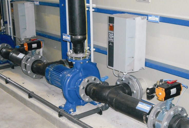
Frequency regulation is optional and depends on the operating conditions. Frequency converters are used for direct installation (power up to 26.4 kW) and for installation in wall or switch cabinets (all ratings).
The decentralised, integrated or compact drive solution, in which the frequency converter is directly attached to the motor, provides better coordination between the motor and converter since the problem of electromagnetic compatibility (EMC Directive EN 61800-3) is minimised.
Regulation of PM motors
Construction series herborner.X-PM/ herborner.F-PM/ UNIBAD-PM/ UNIBLOCK-GF-PM/ WATERblue-H-PM/ UNIVERS-P/A/T-PM...
With the introduction of the PM motor (permanent magnet motor) IE5, which is currently the highest energy efficiency class for motors, the pump system receives further impetus in regard to energetic optimisation. Permanent magnet motors cannot be connected directly to the mains, but rather run only by a frequency converter. The use of these energy-efficient motors is thus an additional factor in favour of a frequency converter.
A special feature of the PM motor/frequency converter combination is the process-optimised regulation of the frequency converter and the resulting energy savings. In this case, the advantages of PM motors over conventional three-phase asynchronous motors can mainly be seen in the reduction of low outputs when speed is decreased.
Duty point control by means of frequency converter
The basic concept behind the frequency regulation of pumps is speed adjustment. This gives rise to
1. energy savings if there is a change in duty points and/or
2. a reduction of flow rate and/or adjustment to the system requirements.
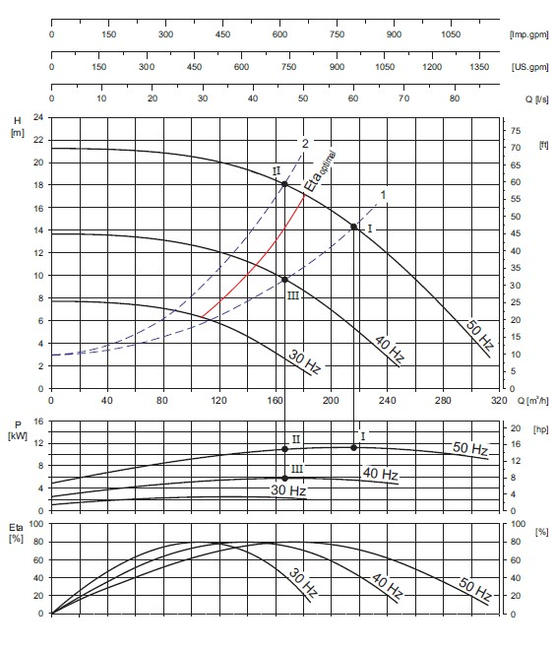
Point 2 is an alternative to the possibility of adapting pumps to meet changing operating conditions. Choke regulation has mainly been used up until now for this, which exerts an influence on the resistance parabola of the system by means of slide valves or diaphragms. In this case, the resistance parabola 1, for example, changes into the altered resistance parabola 2 (see diagram).
By way of comparison, when actuating the pumps by frequency converters, the duty point of the pump under frequency regulation migrates along the original resistance parabola 1. The resulting energy savings are shown in the performance diagram (Q-P set of performance curves) in the difference between Point II and Point III.
Frequency regulation is used predominantly, however, for saving energy with changing duty points (generally two). By applying the example mentioned above, the power input for the pump is reduced from Point I to Point III in the Q-P set of characteristic curves.
If the speed falls below a value at which no acceptable establishment of the flow can take place, the laws can no longer be applied. While it is true that the values Q, H, P and Eta are in line with one another, turbulence and air in the medium lead to imprecise measurement. For this reason, there are limits imposed on frequency regulation.
It is ultimately important when looking at system optimisation to take optimal efficiency into account also (Eta optimal). This also has an influence on matching the best possible pump to the system.

The energy savings generated from frequency regulation can be calculated using the similarity rules for centrifugal pumps. Centrifugal pumps achieve the greatest energy savings potential. They are fluid kinetic machines with a square torque curve for which the adjacent proportionality laws apply.
The decisive factor for the energy savings is the cubic relation between speed and energy consumption. A pump running at half speed requires an eighth of the output required for operation at full speed.
Example of using a frequency converter in swimming pool technology
Ночное снижение затрат
| Рабочая точка: |
Q = 215 m3/h H = 14 m P = 11,5 kW |
| Ночное снижение затрат путём выключения одного насоса: |
Q = 170 m3/h H = 11 m P = 5,5 kW |
| Частотное регулирование от двух насосов: |
Q = 107,5 m3/h H = 6 m P = 4,5 kW |
| Energy savings by night-time energy reduction: | ΔP = 1,0 kW |
| Operating hours per year in night-time energy reduction: | 3000 h |
| Экономия: | 3000 kWh |
|---|